
 Božek’s chronometer

During the great repair in 1866, it was, among others, decided that it is necessary to considerably increase the accuracy and reliability of the machine’s operation. This was not feasible while maintaining the control of the going machine by the spindle step. The project of completion of the clock with a precise controlling chronometer that would release the old machine every minute was entrusted to Romuald Božek (1814–1899). The crown wheel was removed from the original machine, the step wheel was discharged and a trigger controlled by an external chronometer was installed. Today, we would probably resolve such task relatively easily. We would insert an electronic control unit before the old machine of the clock; the unit would release the original machine in intervals corresponding to the original crown wheel.
Even in 1866, the task was resolved at hi-tech level of its times. It was necessary to build a robust chronometer that would be sufficiently precise under very fluctuating climatic conditions and without an influence of the machine’s operation on the oscillator. At that time, some methods of enhancing the accuracy of operation were already known. Above all, the machine needed to be controlled by a pendulum with a temperature compensation. The step of the machine had to be a step with constant impulse force to reduce the influence on the time of awing to the minimum. Romulad Božek was inspired by the method that had been used for one of the biggest tower clocks – the clock in the tower of the Westminster Palace – the clock called Big Ben after the bell used with it. In the picture from 1866, the machines are exhibited prior to installation to the tower. In the background, there is the Božek’s chronometer, in the front can be seen the main machines of the clock with already modified going machine.
For the chronometer of the Prague Astronomical Clock, a pendulum with temperature compensation by mercury was used. It has 25 kg of mercury. The thermal dilatability of the mercury in the pocket of the pendulum compensates the variation of the length of the suspension due to changes of external conditions. Denison’s gravity step with a constant impulse force by means of swivelling arms (Edmund Denison, 1816–1905) reduces the influence of the machine on the time of awing. Another construction detail that enhanced the accuracy of the operation was the insertion of the Dent’s spiral (Edward John Dent, 1790–1853, the leading author of Big Ben) between the driving wheelwork and step. More even rotation was further ensured by means of a slowdown vane. The chronometer exerts a precision of several seconds per week even in case of very different outside temperatures.


It must be noted that the current machine is a copy of the original chronometer, which was destroyed by the fire in 1945.
The trigger of the going machine
The interconnection of the chronometer with the trigger of the old machine is ensured by a thin copper wire. The wire is lead upwards over the glazed door of the recess, where the chronometer is located, to the stopper of the main machine. Once a minute, the stopper is released and the going machine of the clock performs one “step”. The end of the wire is well visible on the third picture of the chronometer.
The mechanism of the twostage stopper itself can be seen in the next picture. It represents a connection of a modern “timekeeper” (as the chronometer used to be called) with the oldest part of the astronomical clock. The trigger was quite sensitively inbuilt in the original going machine. Instead of a crown wheel and spindle, a wheel with lateral tooth system is used. This allows us to orientate the axles of the releasing wheelwork vertically to the existing axles and thus move the releasing arm with a large slowdown vane to the side of the frame. The vane would be on the left of the picture.
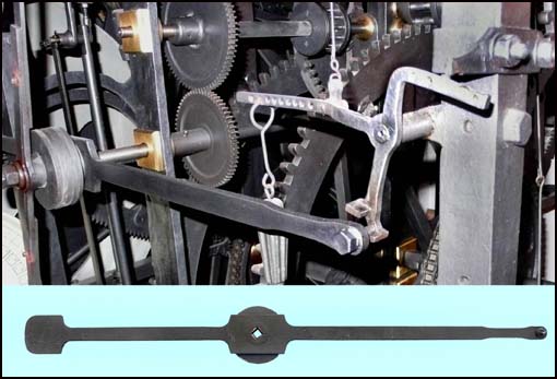
The stopper itself has two stages. Normally, the releasing arm (showed separately on the lower picture) seats on the upper stopper on an angular lever. When the wire is pulled upwards, a “strain” takes place. The angular lever is lifted, the arm is released from the upper stopper and falls onto the lower stopper. This state is showed in the photograph. After the wire is released, the arm slides off the lower stopper, make a turn and stops again on the upper stopper. The angular lever is weighted by a weight that reminds that of a cuckoo clock so that the lever is reliably lowered. One turn of the arm is, by means of two new wheels with frontal transmission, transmitted to a pinion driving the abovementioned wheel with lateral tooth system. The going machine exercises a movement by one minute.
Not long ago, the released going machine required relatively large power reserve for reliable operation. There was an adverse side effect – strong surges in the structure. The current clockmaster managed to change the balance of the releasing arm in a nondestructive way so that it was possible to considerably decrease the pulling force exerted by the weights and thus achieve smoother operation. For the control of the operation, the today’s clockmaster uses a clock controlled by the DCF radio signal. With some exaggeration, we can say that the Prague Astronomical Clock, with the help of the clockmaster’s hands, measures the time with the precision of an atomic clock even after 600 years.
